
Stereotomy
Studying the art of the line.
Stereotomy is like a computer modeling program from the middle ages, that uses handmade drawings to compute highly complex 3D geometry without the use of numeric math. This drawing technique has distinguished histories in some parts of the world, most notably France, Germany, and Japan, where it was (and still is) used to create renowned works of architecture like cathedrals, castles, Buddhist temples, teahouses, and more.
With the sole use of simple drafting tools and a steady hand, one can use stereotomy to intuitively explore 3D space and become more adept at visualizing complex intersections. This subject is a passionate interest of mine, and there are many applications of stereotomy in the world of timber framing and fine woodworking.
How does it work?
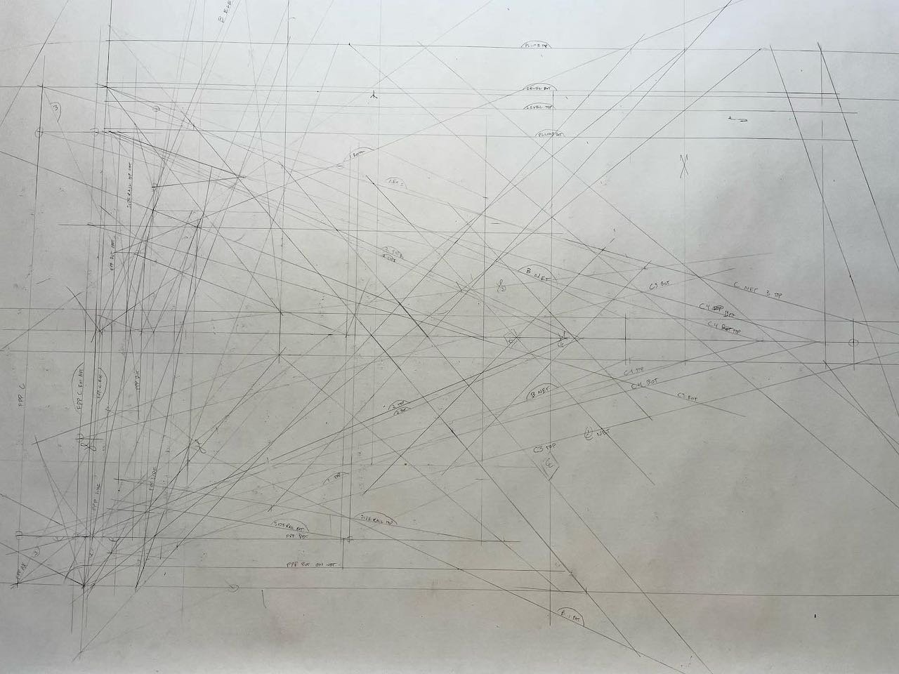
Instead of relying on numbers and equations to solve geometry puzzles, stereotomy does its computing physically using lines on a page. With projection and proportion, one uses the drawing to translate between different views and ultimately discover the angles and distances desired for laying out timbers (or stone, or any other solid material).
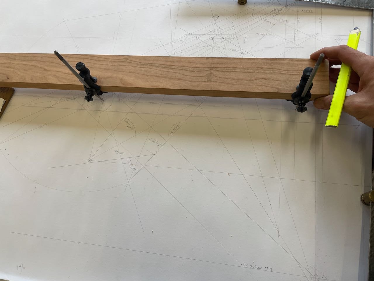
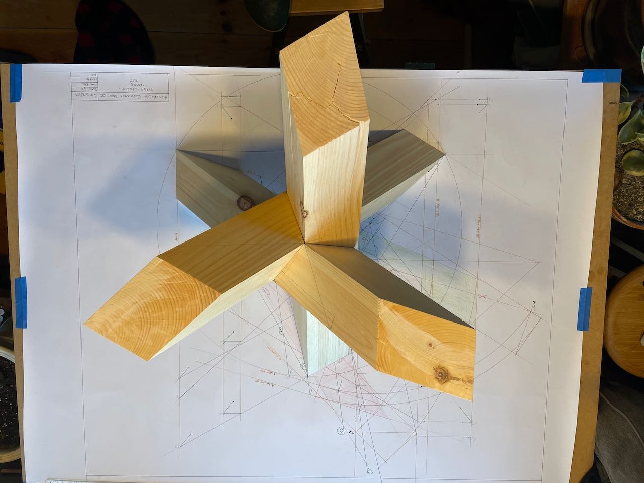
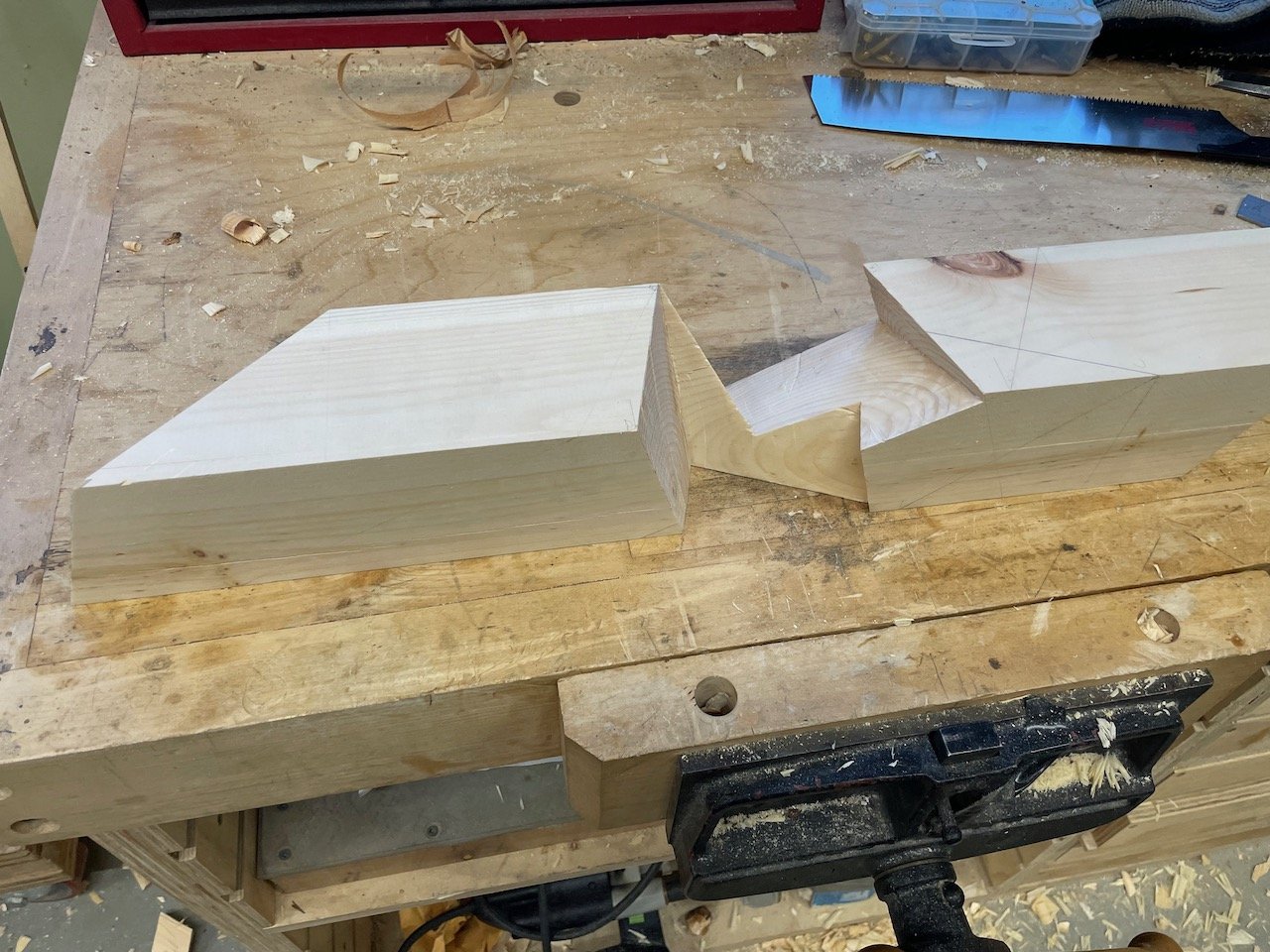
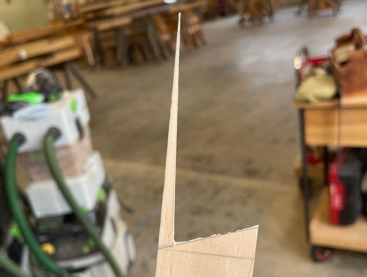
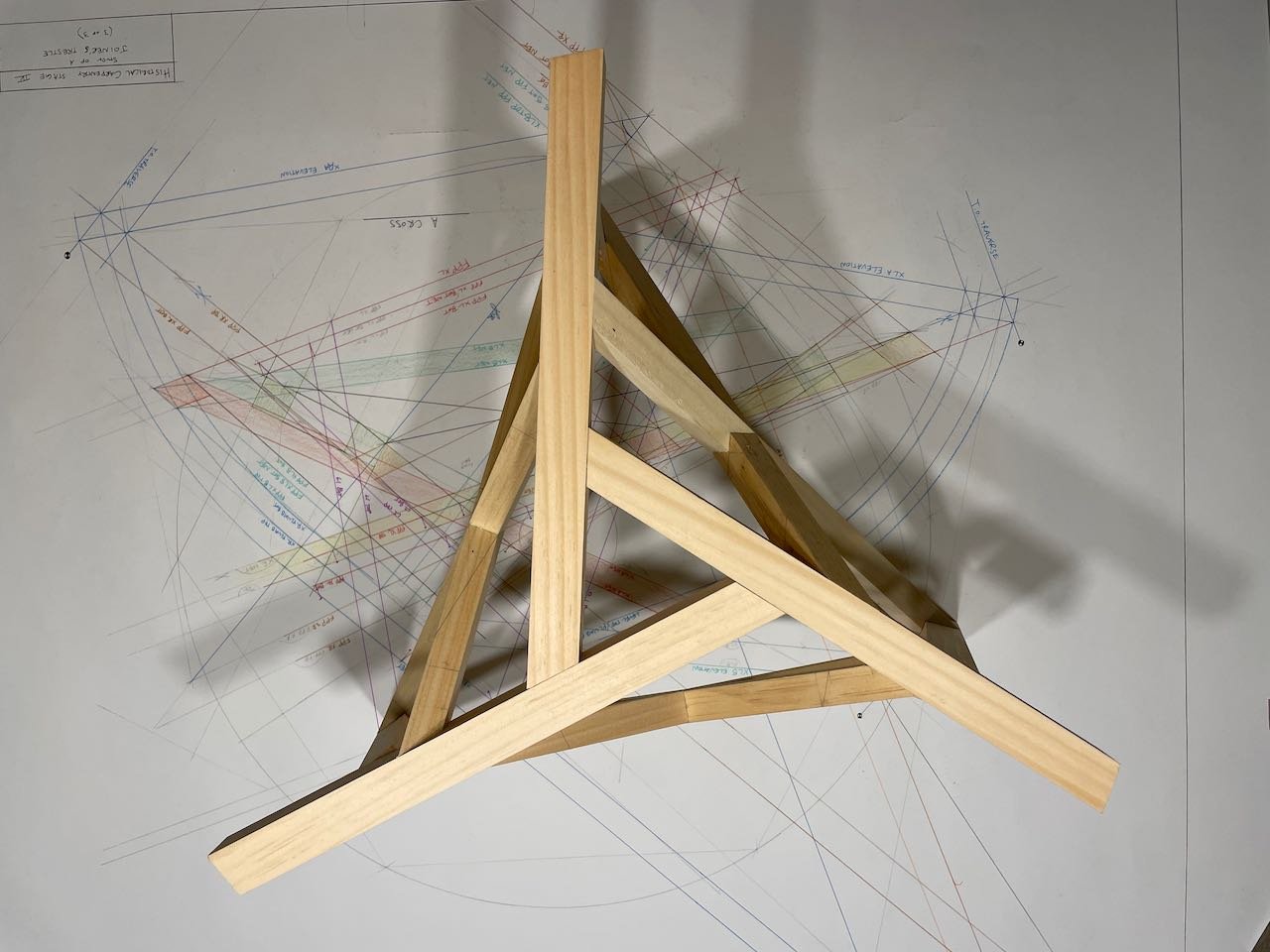
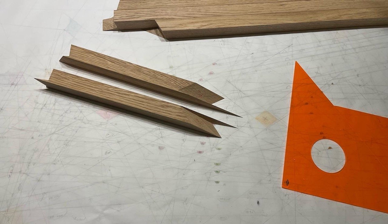
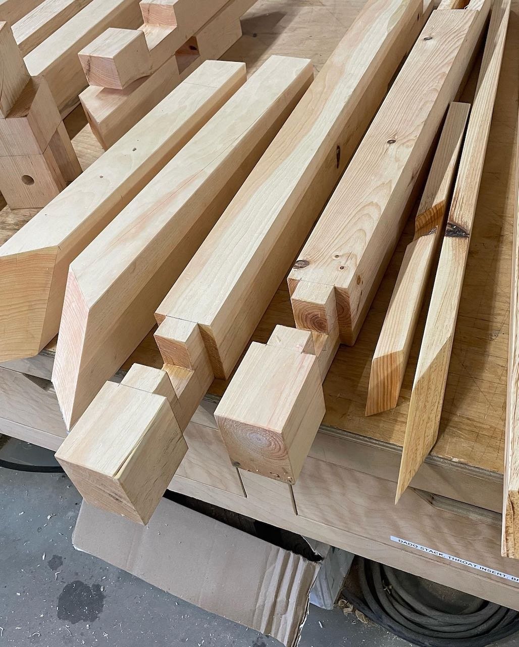
This image illustrates how the lines in the drawing represent the actual shapes of the layout, in this case on a part for a study model. Each piece of wood is laid on the drawing in its particular place (or places), and the desired lines are “lofted” up onto the workpiece with a series of tick marks.
What can you make using stereotomy?
Well, sky is the limit…
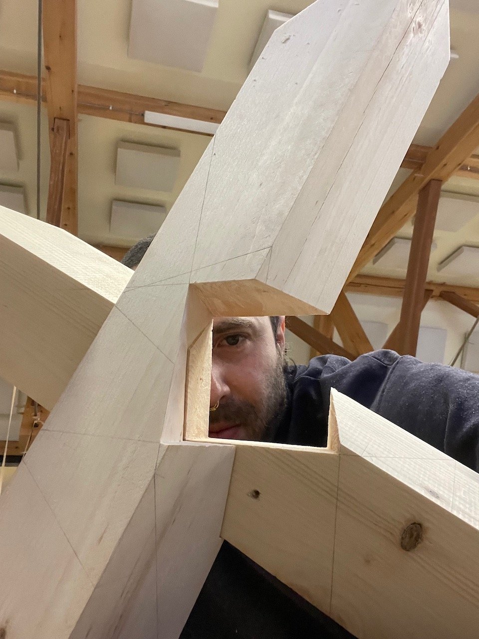
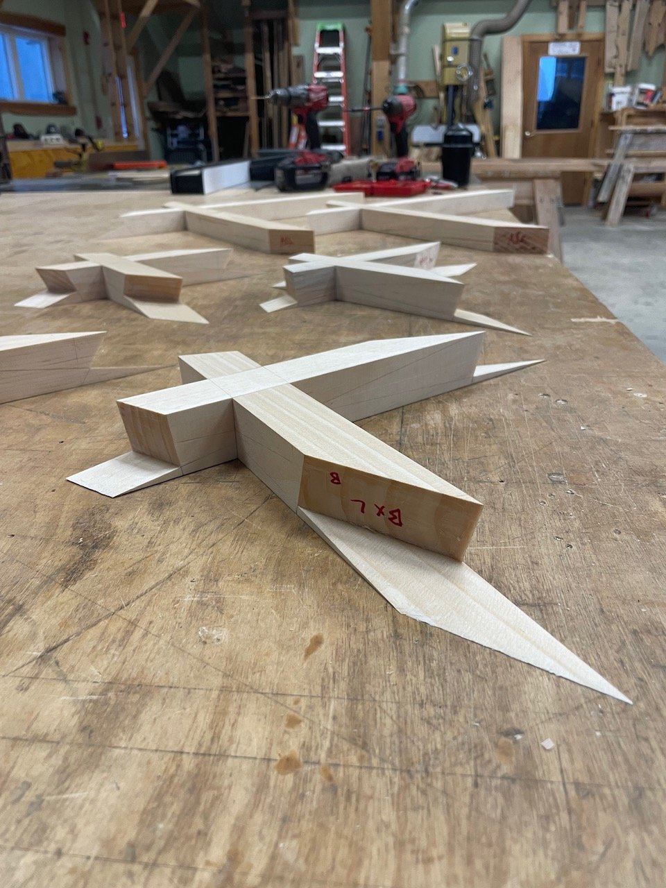
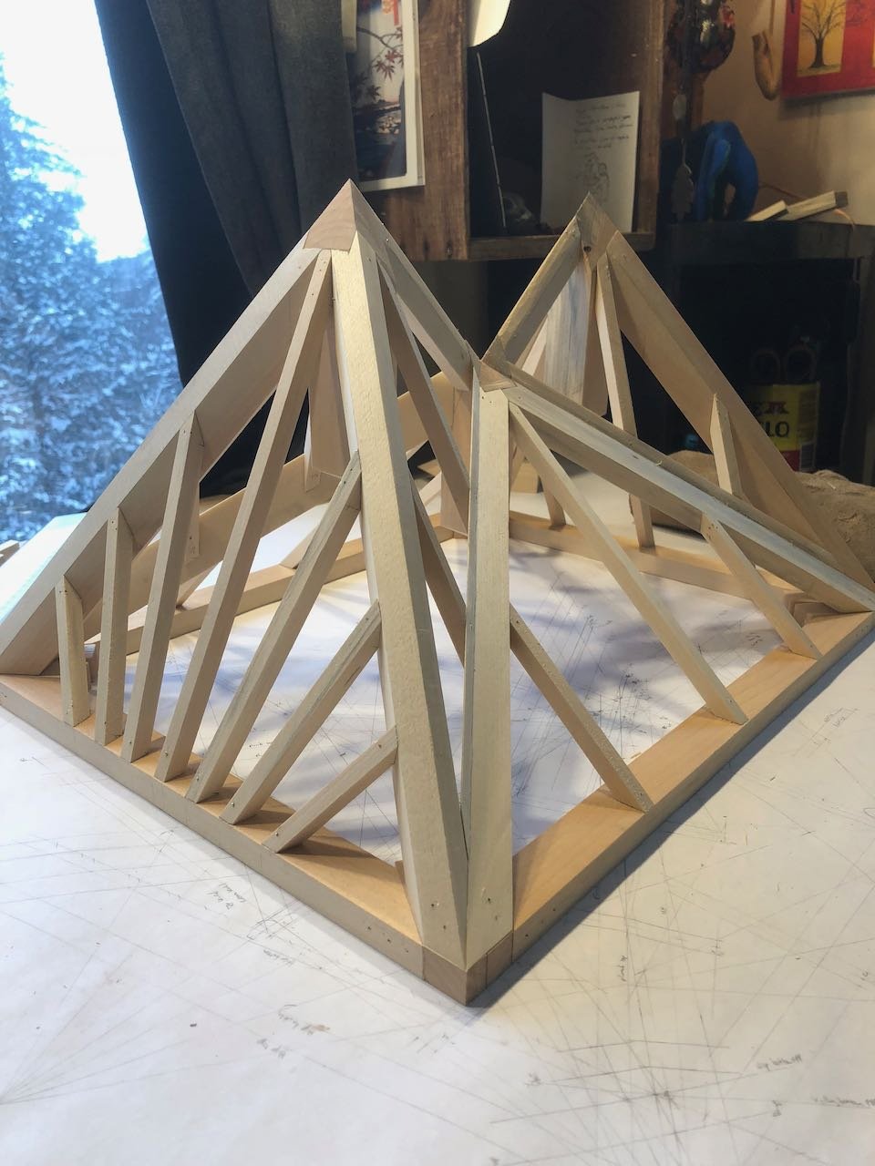
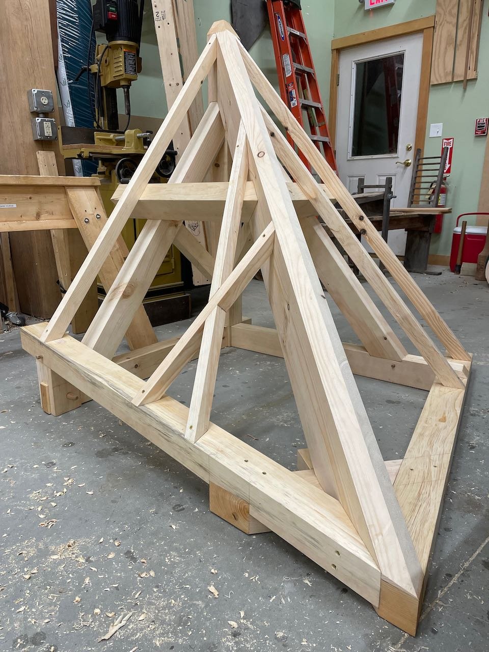
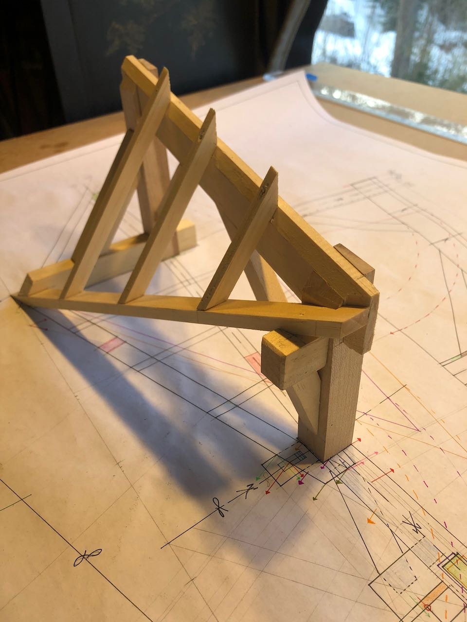
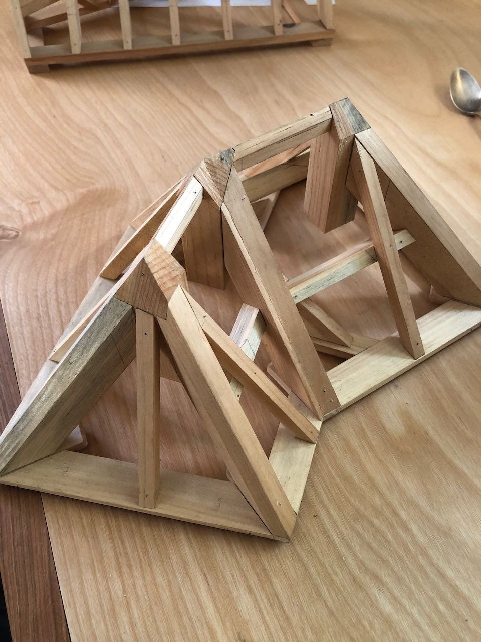
Three intersecting pyramids.
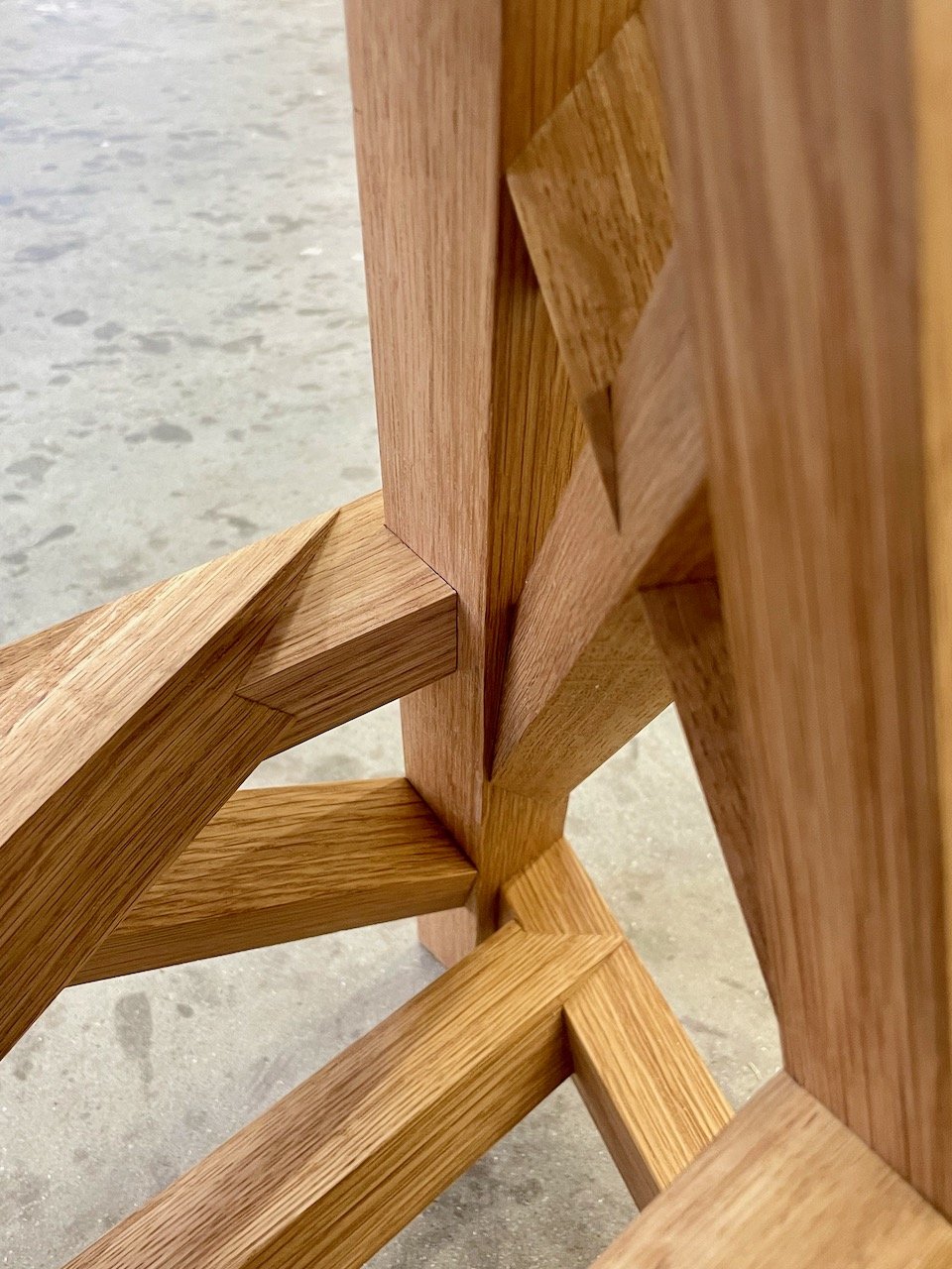
Stereotomy joinery, pre-assembly.
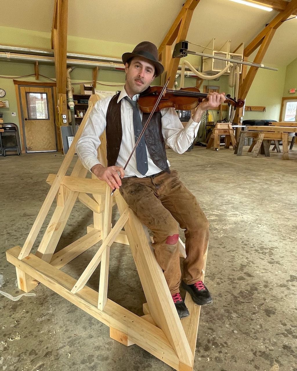
Stereotomy joinery, post-assembly.
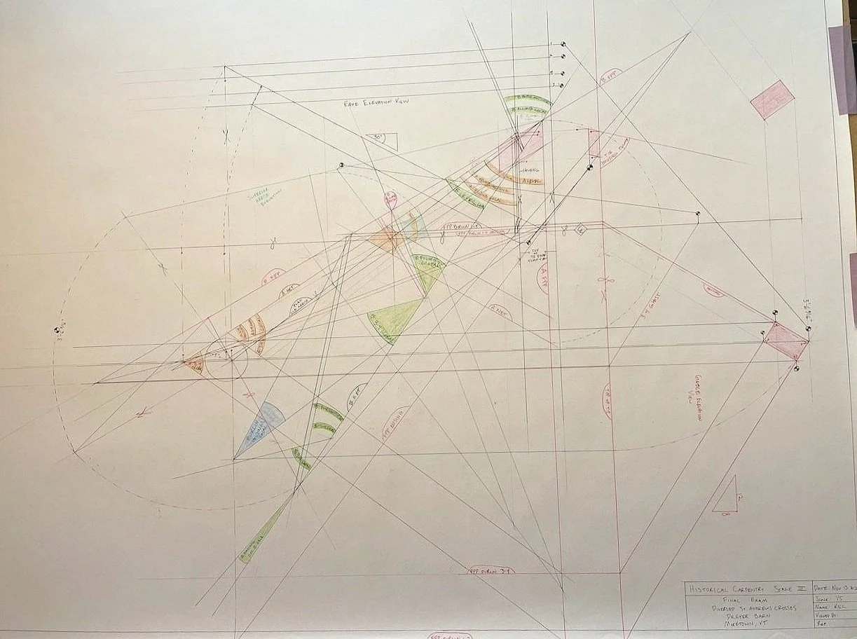
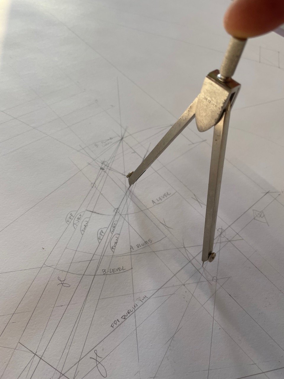
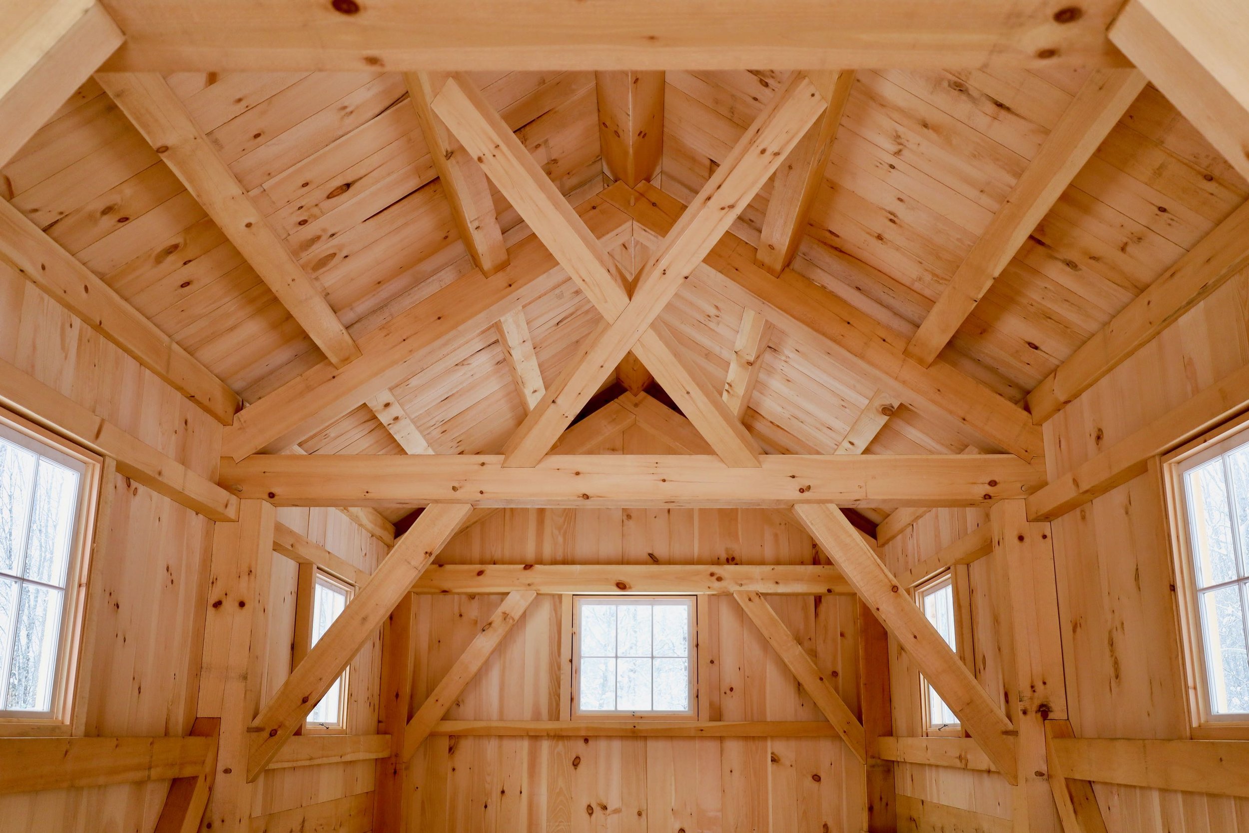
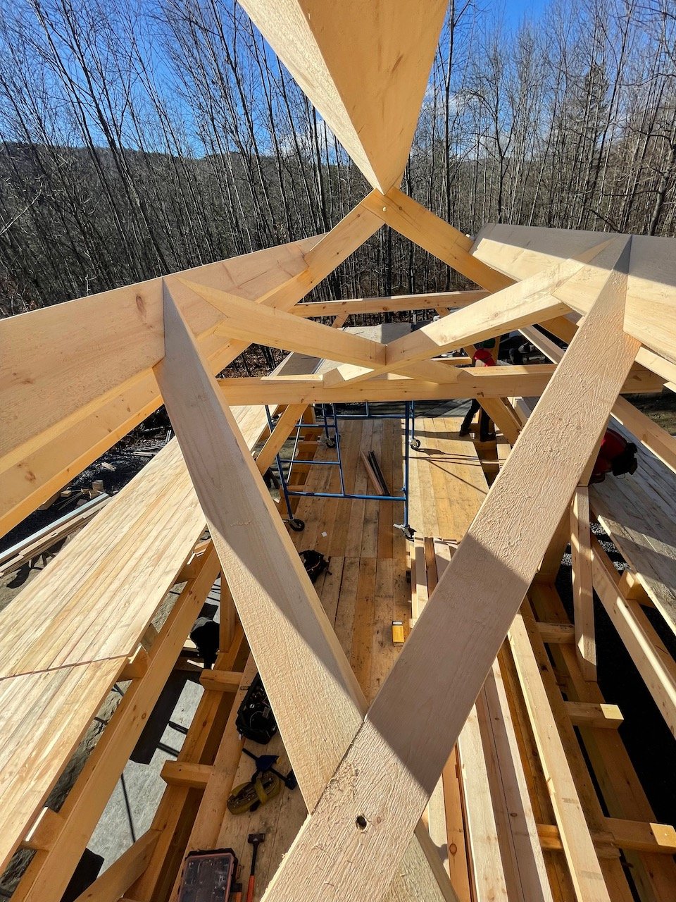
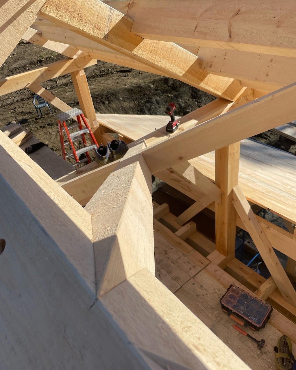
Full Scale Timber Stereotomy
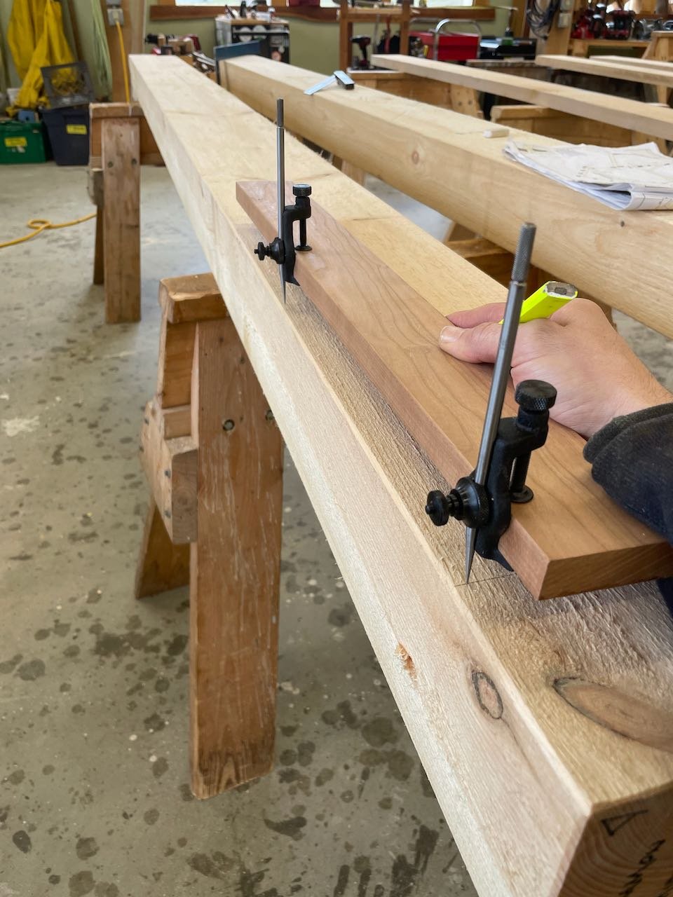
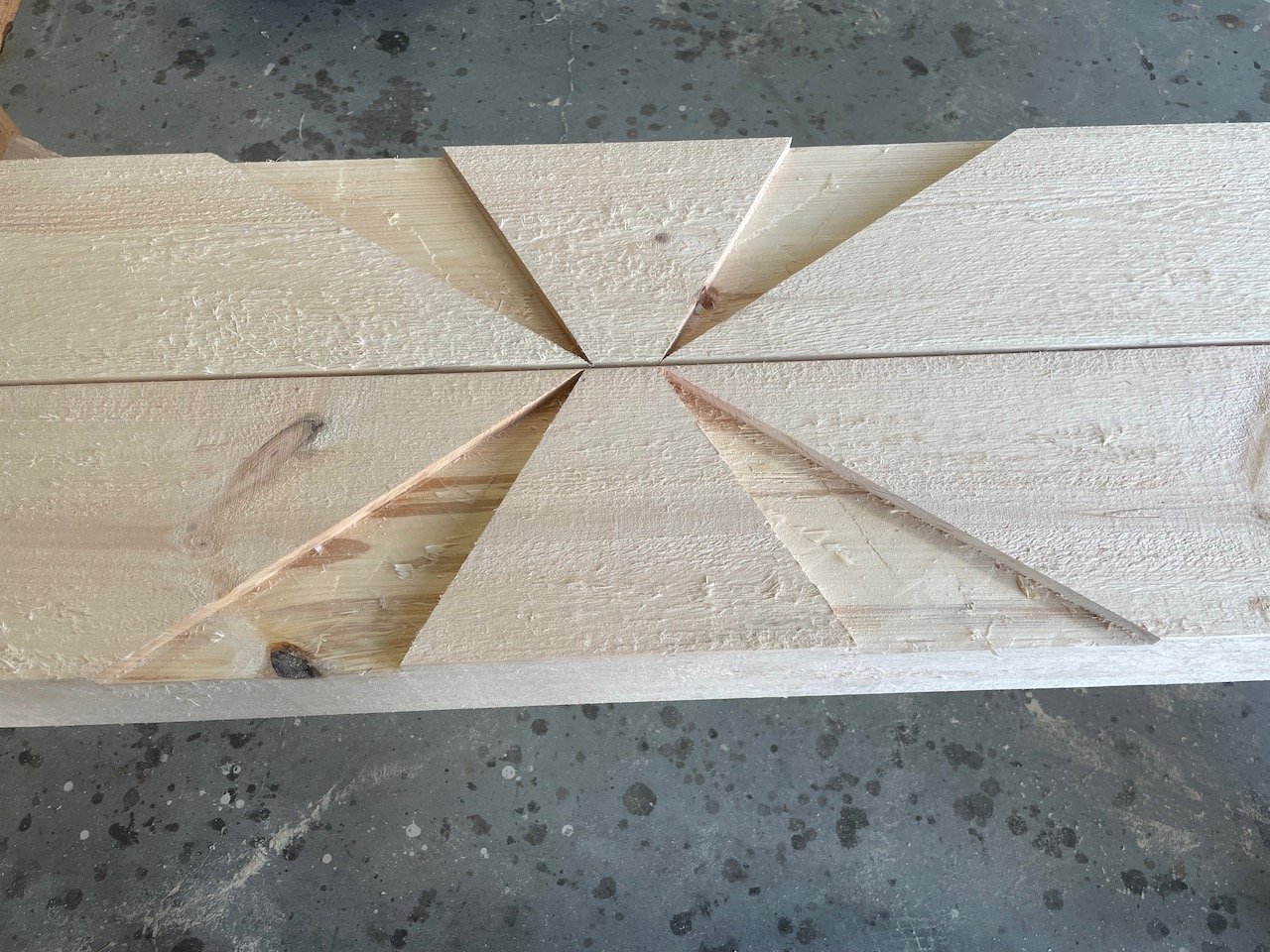
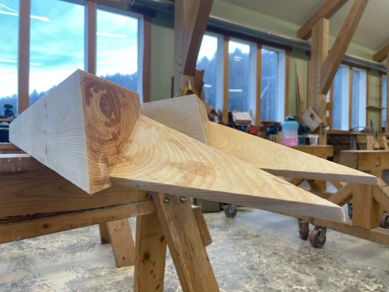
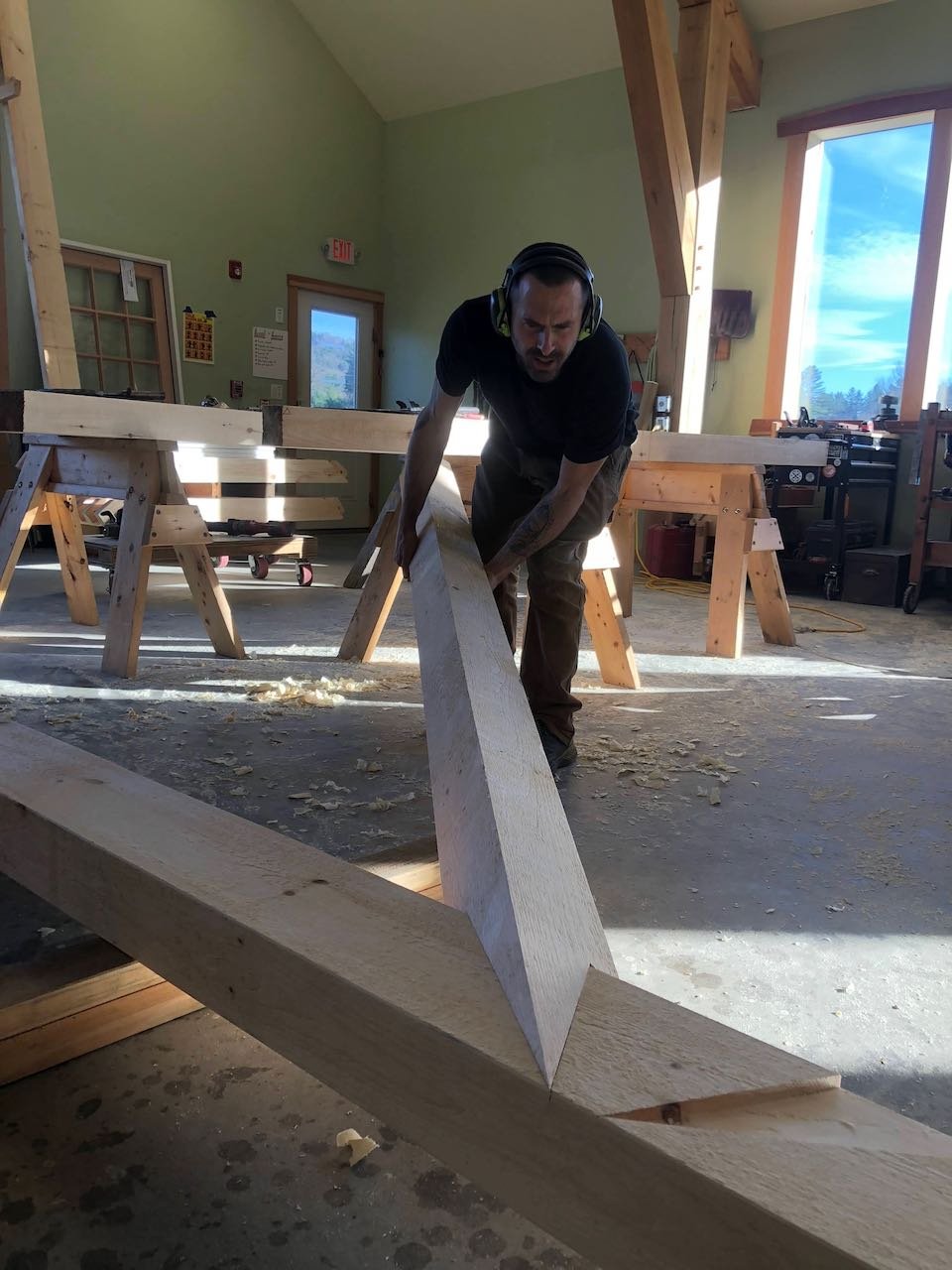
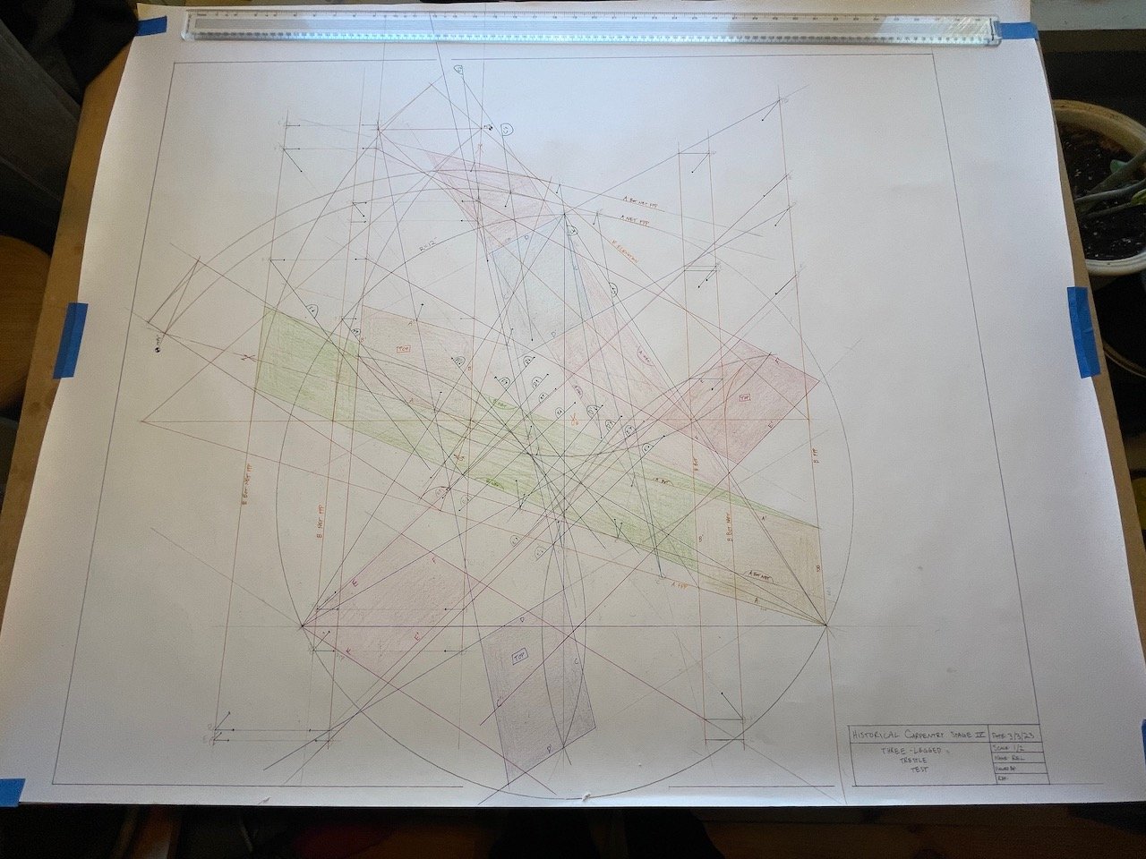
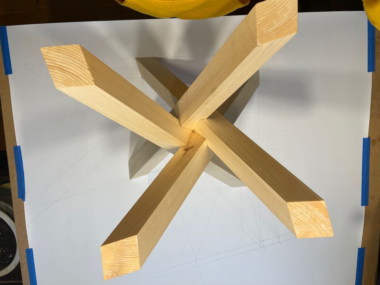
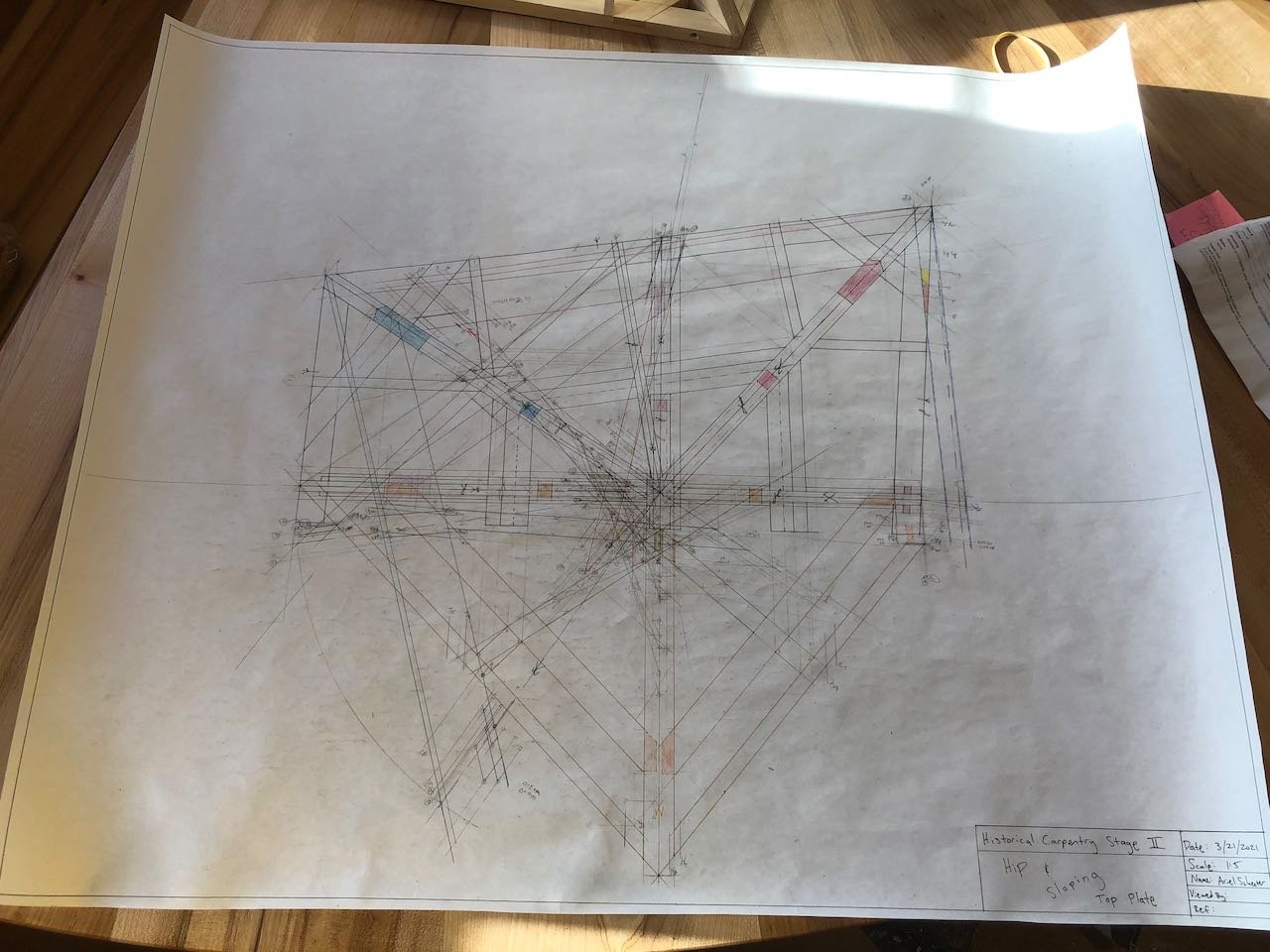
In the Stereotomy Barn project, I worked off a 1:5 scale drawing, shown here. I used dividers and other tools and tricks to translate information from the page to the timber. Everything needed to make the unusual pairs of X-braces in the roof of this barn was derived from the drawing. See below for pictures of the process.
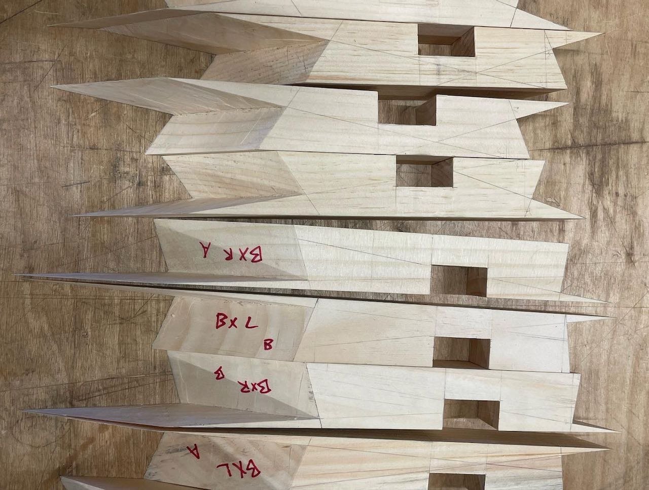
More Stereotomy Models and their Drawings
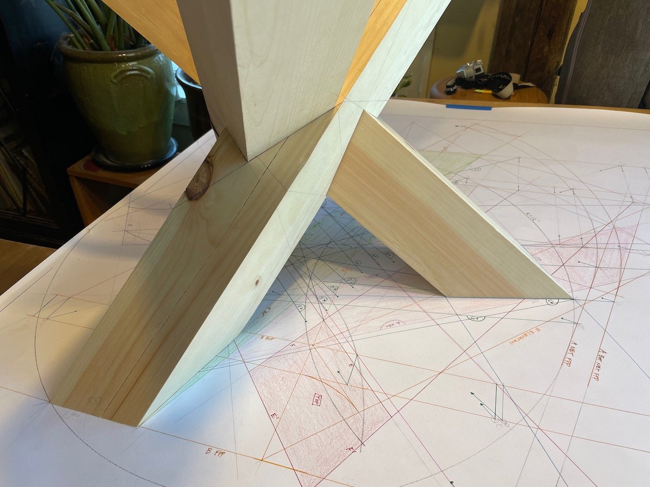
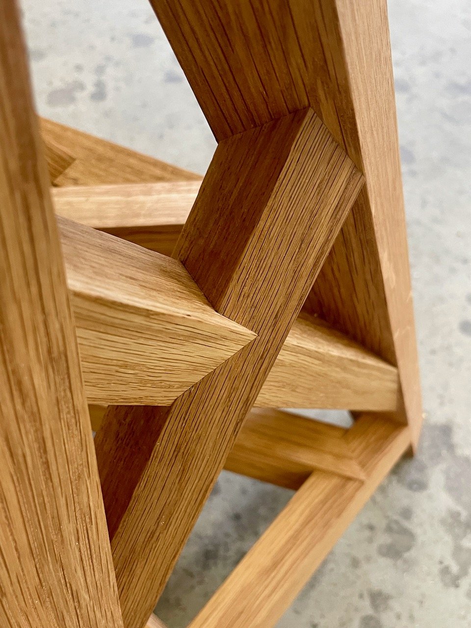
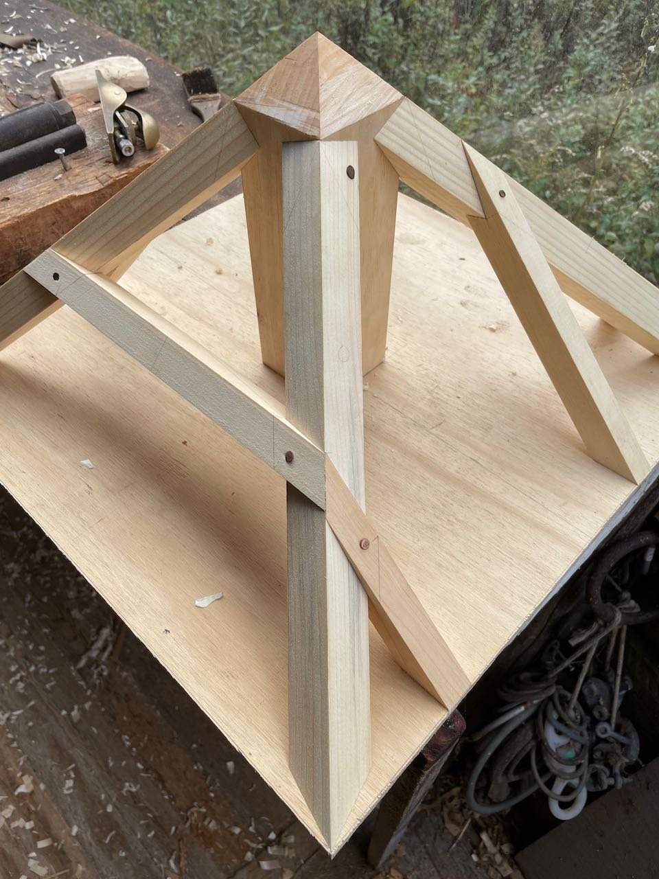
This model has three legs whose feet land inscribed in a circle. One piece is notched out for one of its neighbors, one piece is notched out for both of its neighbors, and one piece remains completely uncut and slides through both its neighbors to form a seamless intersection.
Three-Legged Trestle
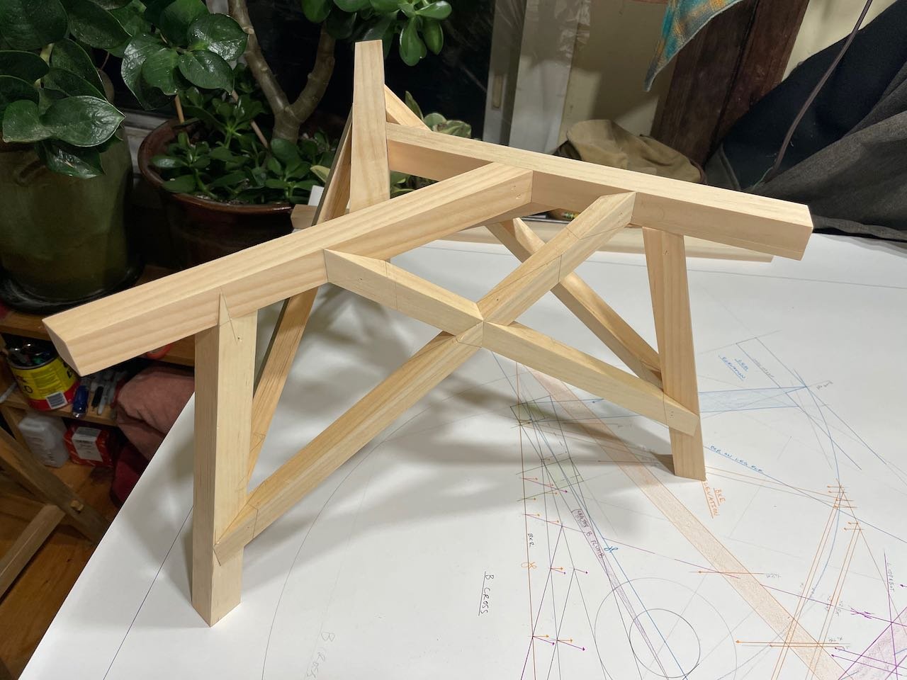
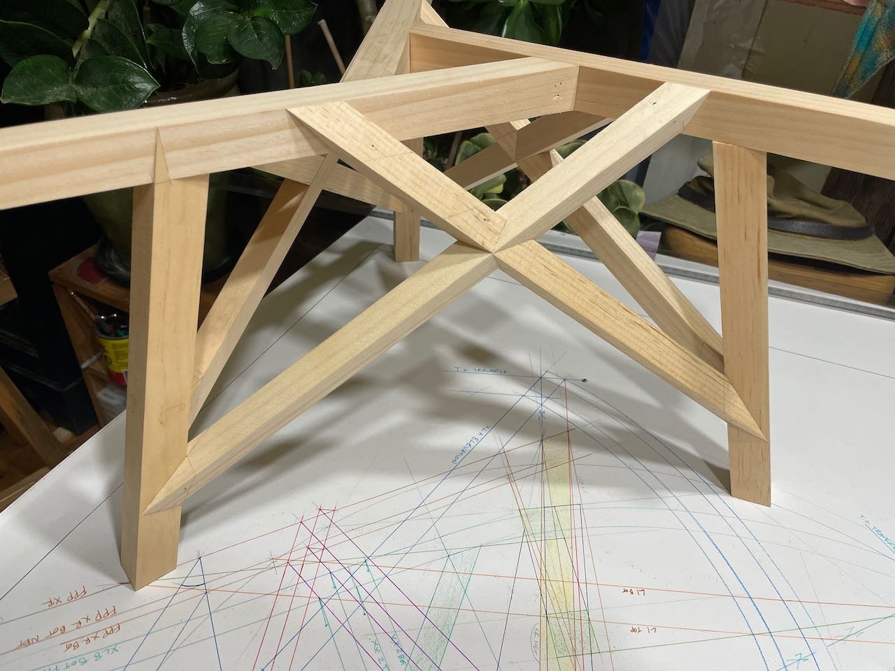
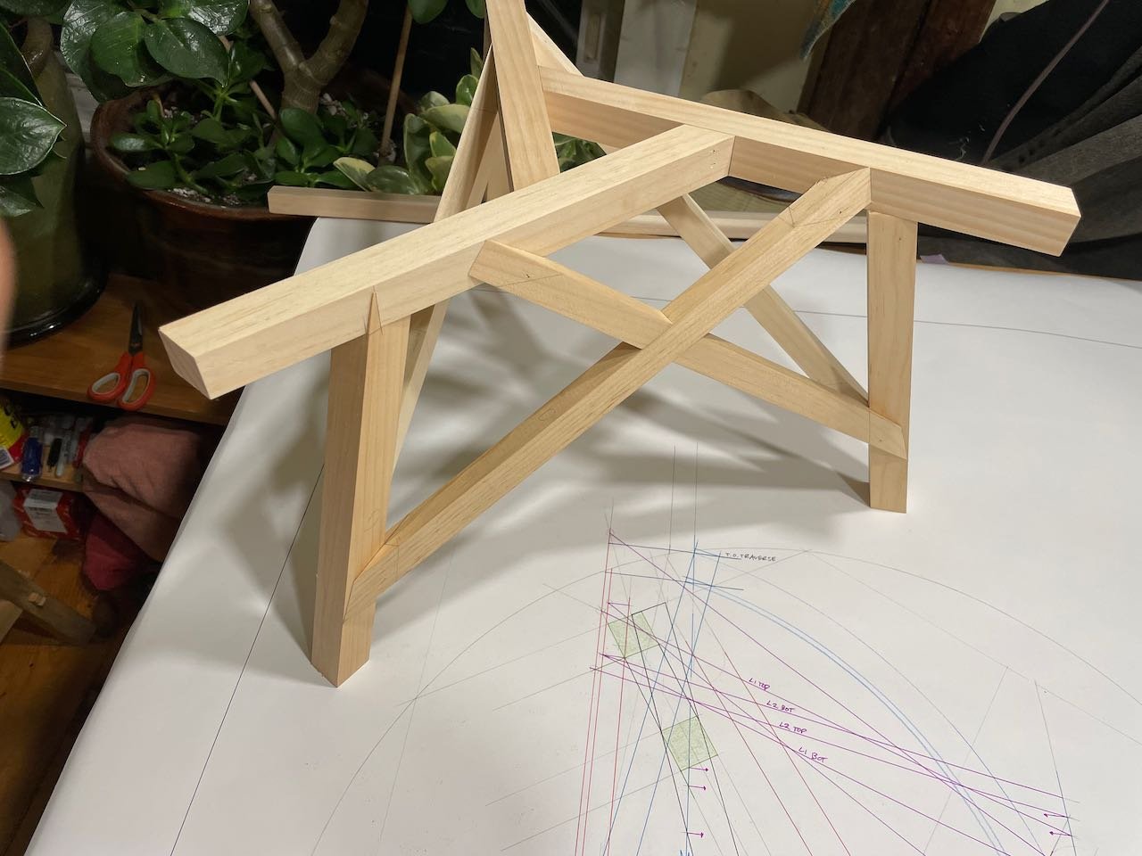
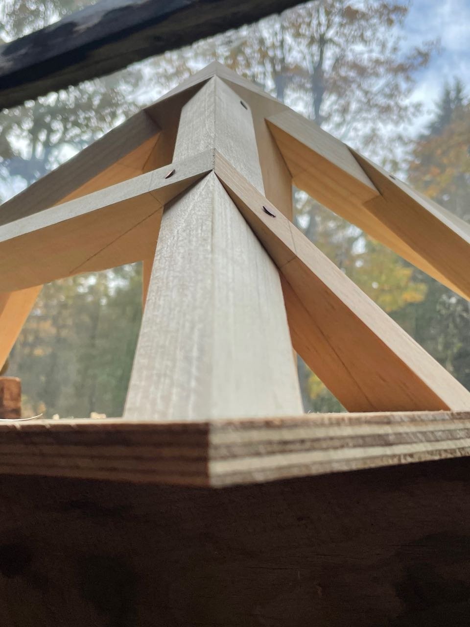
The Moore Trestle
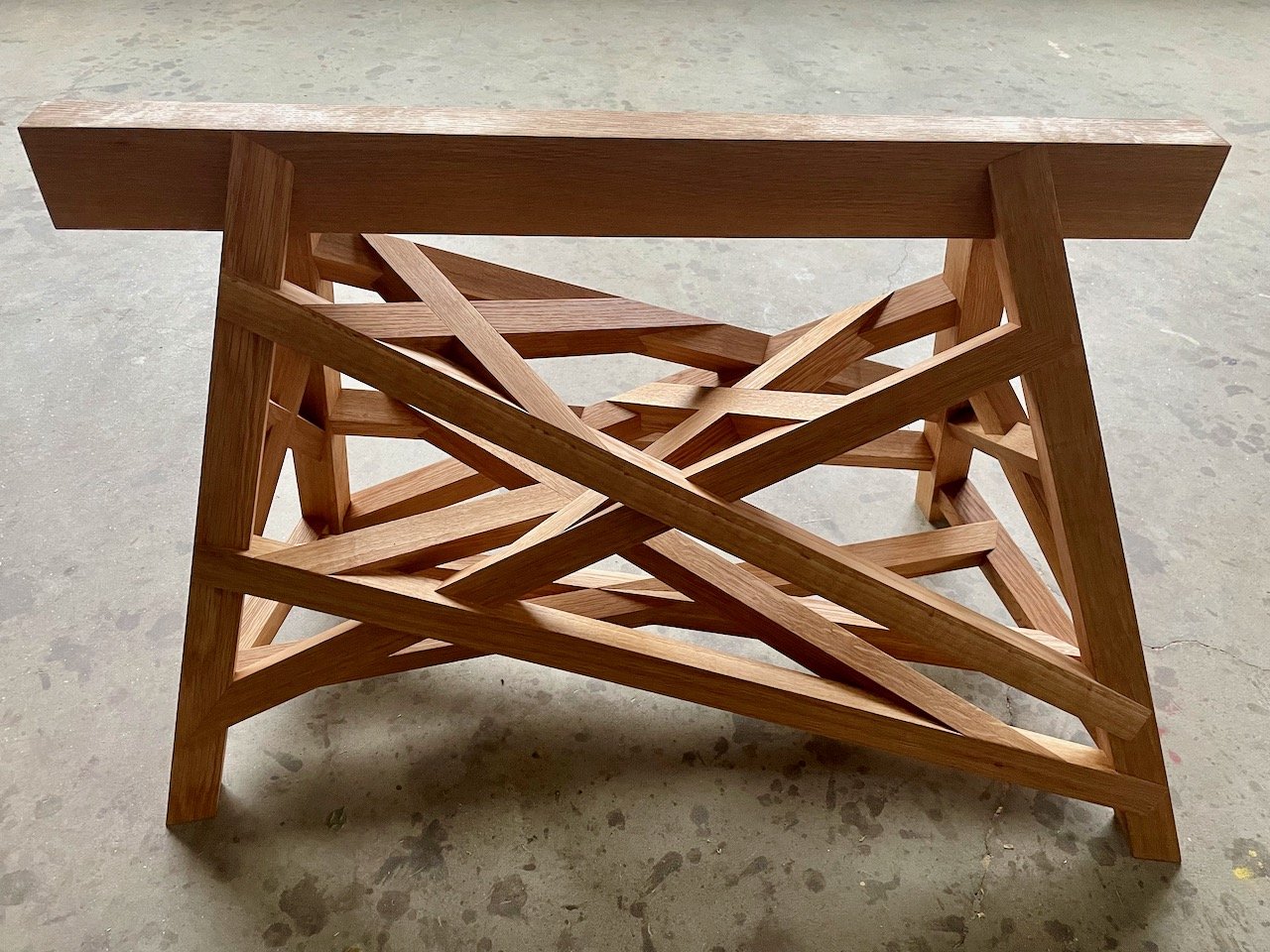
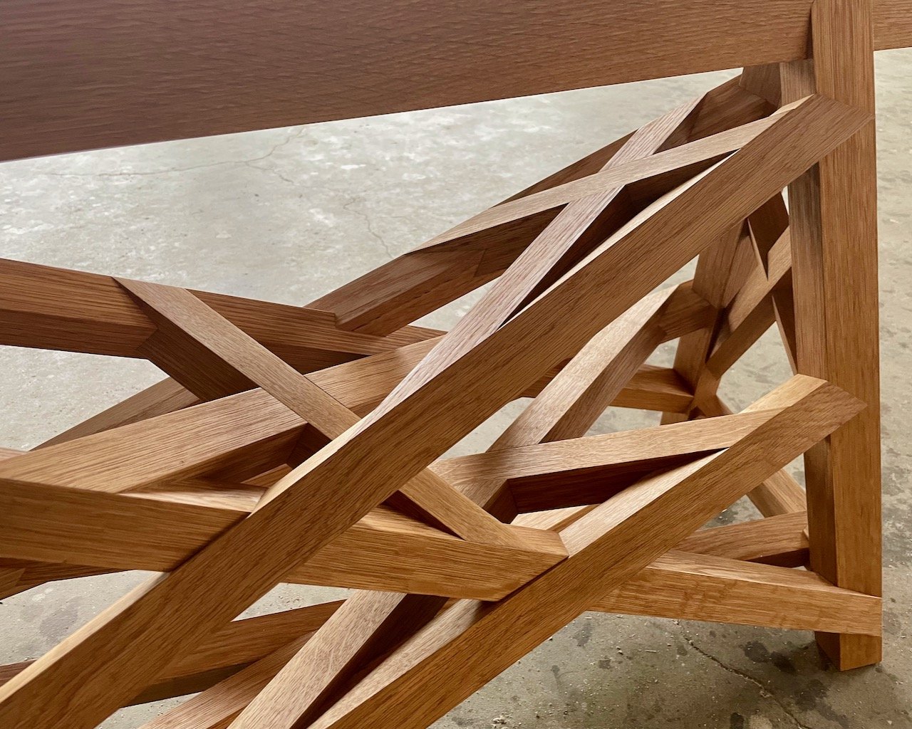
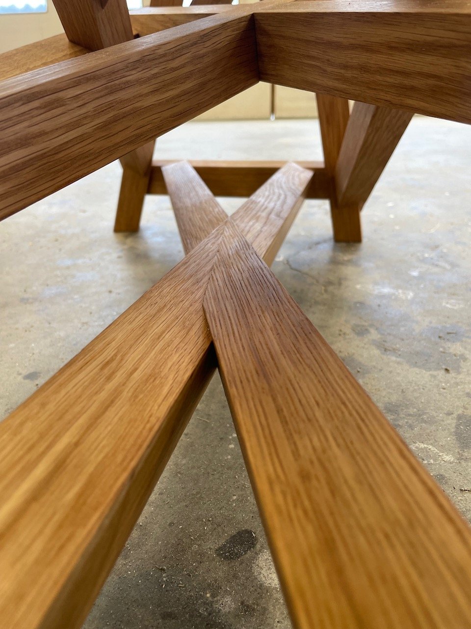
This trestle has delicate barbs all over it! X braces on X braces on X braces.
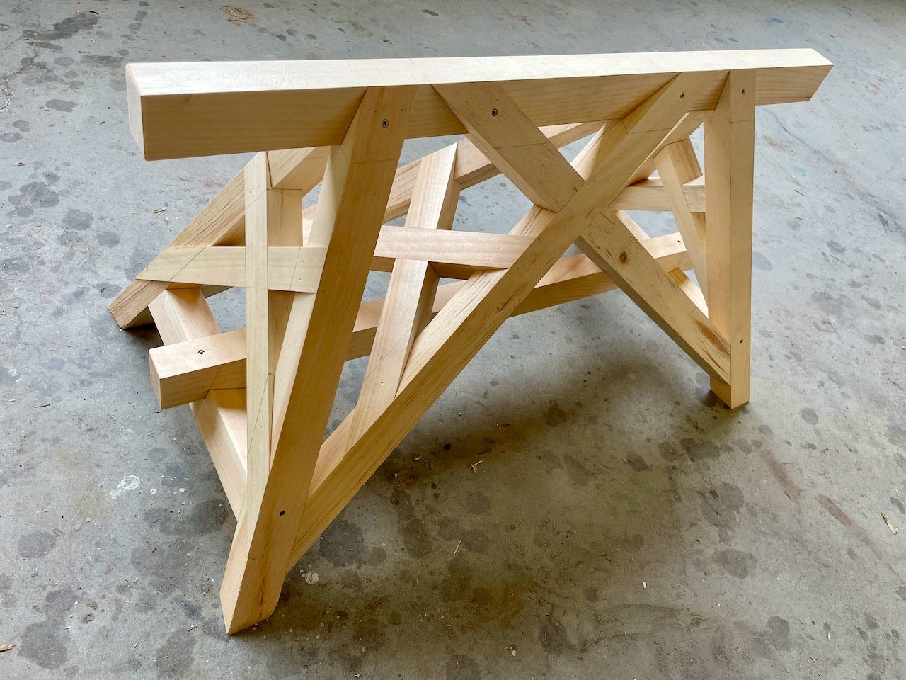
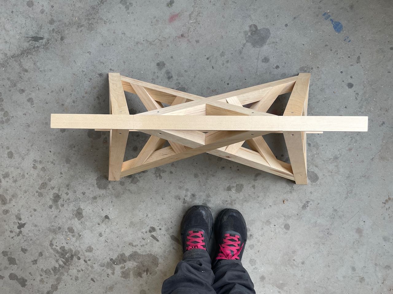
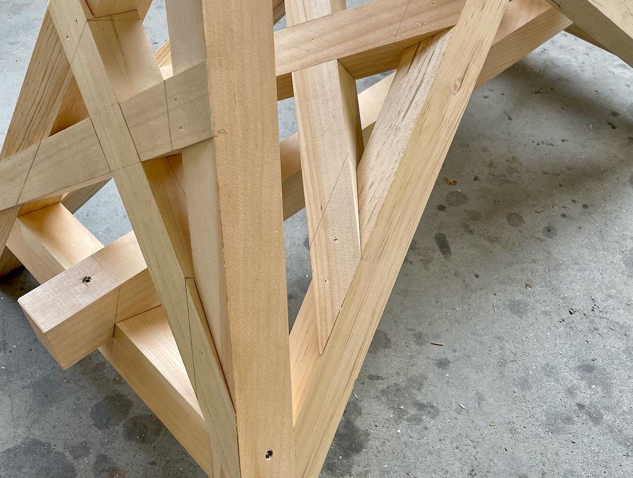
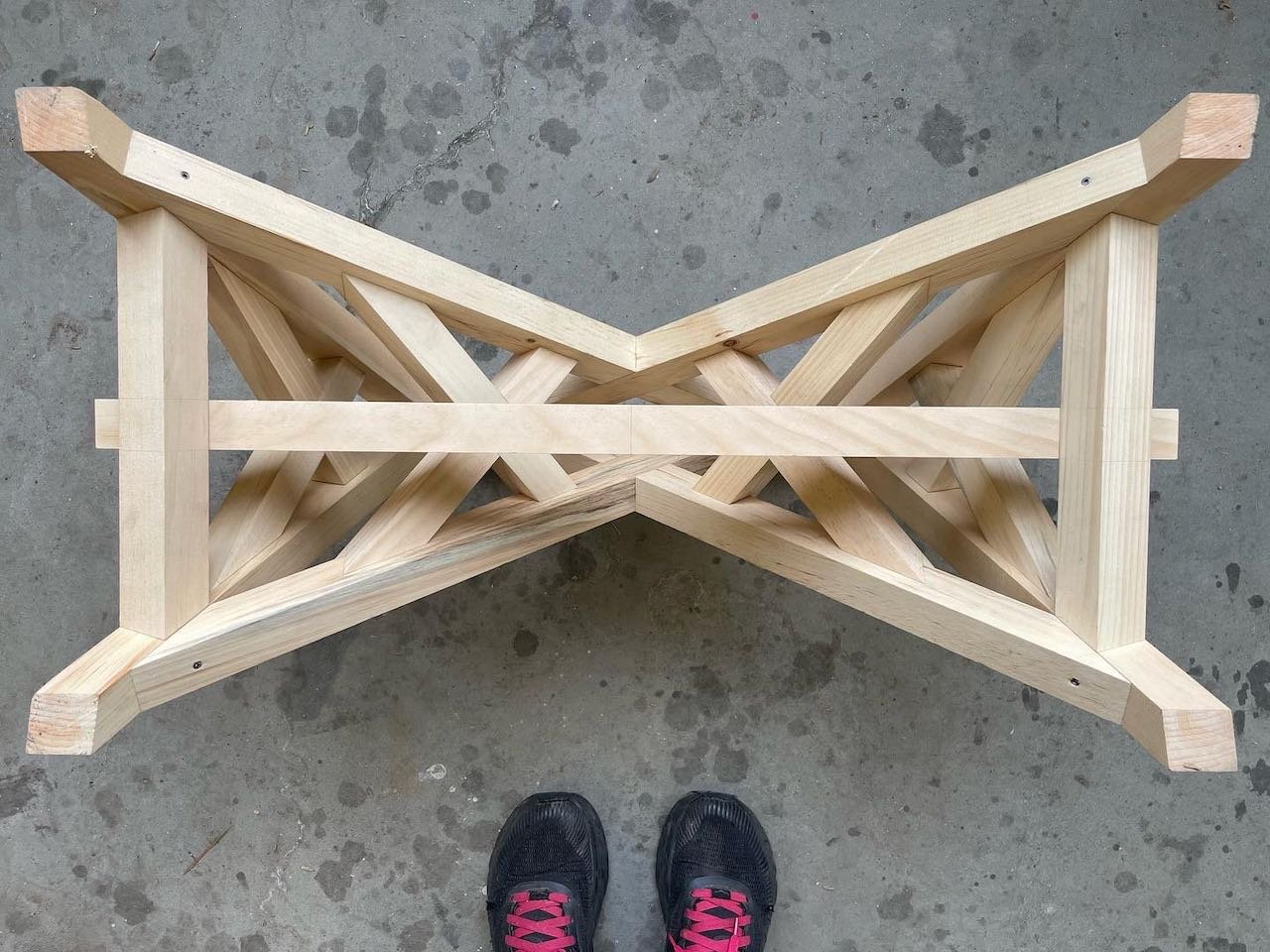
Joiner’s Trestle
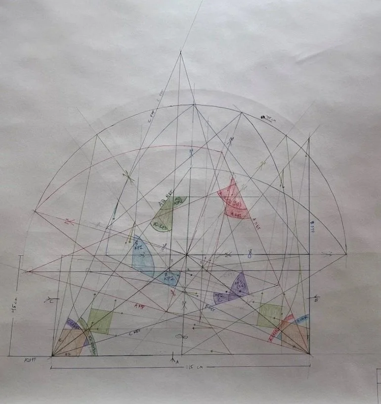
A three-legged trestle inscribed in a circle on the page. Each of the three “bays” features a St. Andrews cross, with each piece rotated along its axis in a different orientation: one cross is half-lapped, one cross has plumb faces, and one cross has each piece aligned with the upper edge of its corresponding top beam. This creates unique geometry at each leg intersection in each of the three bays.
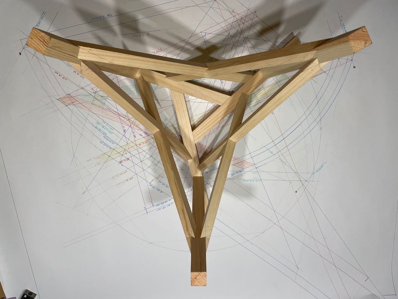
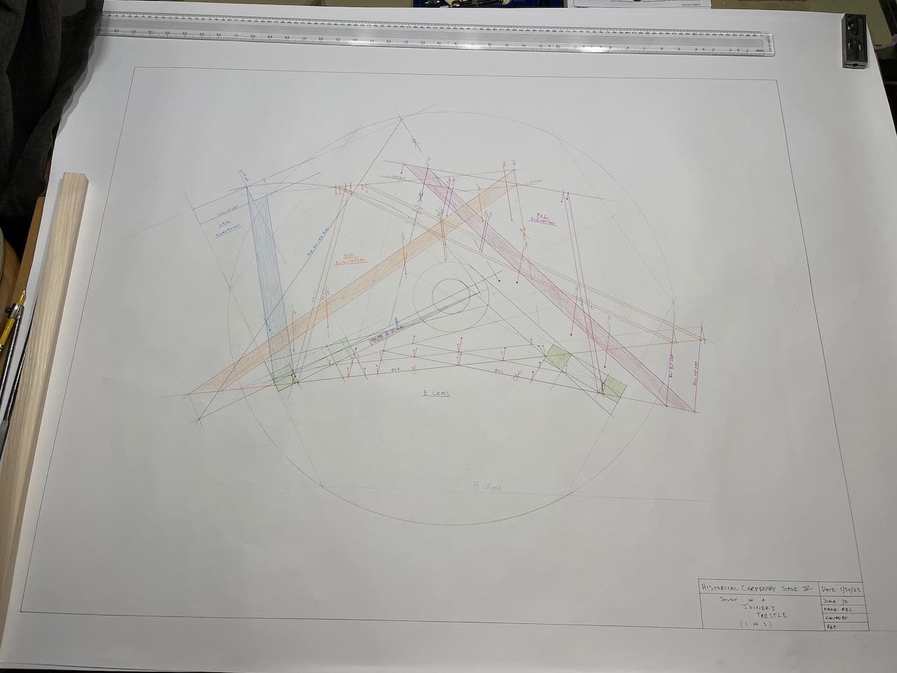
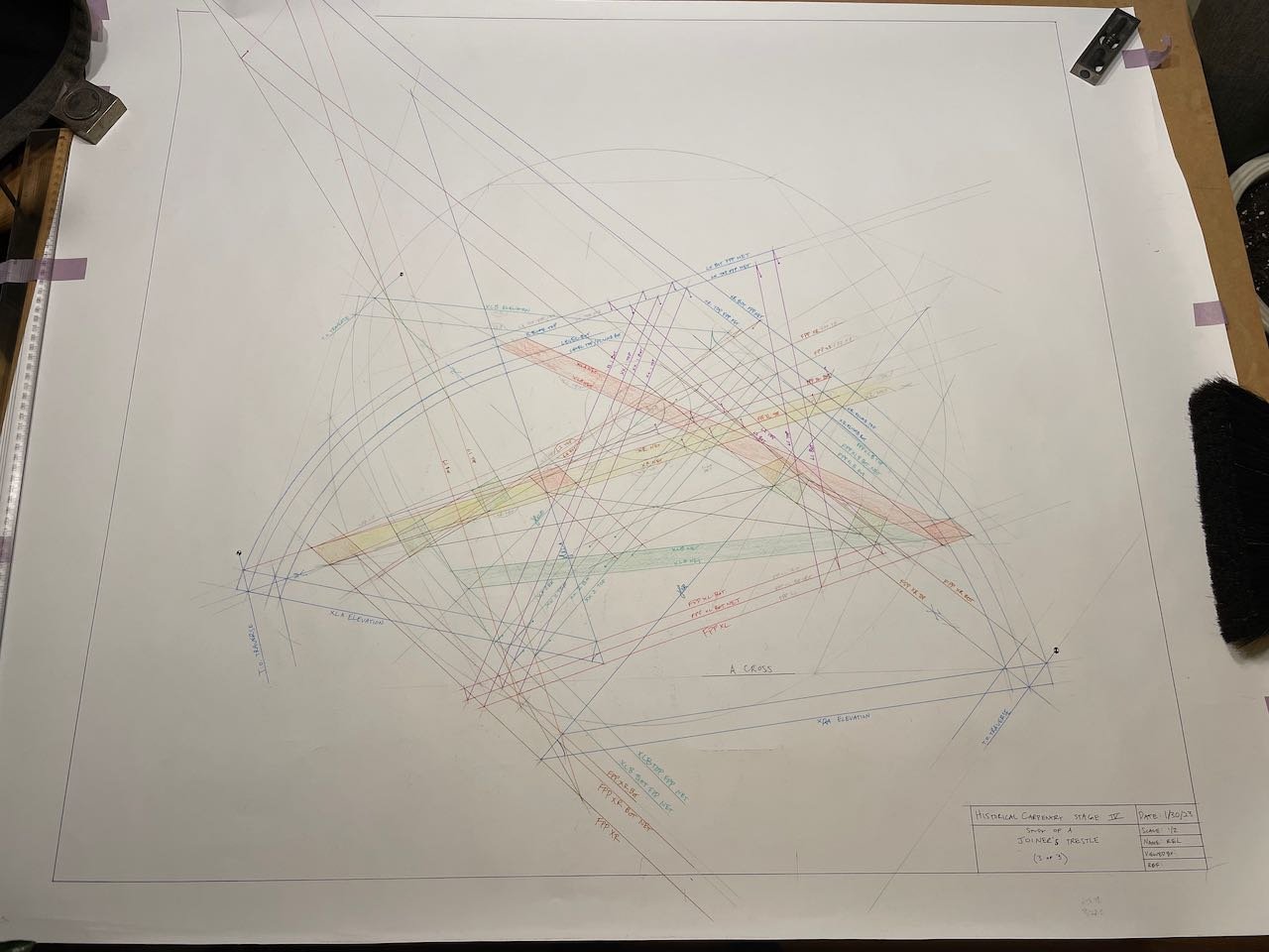
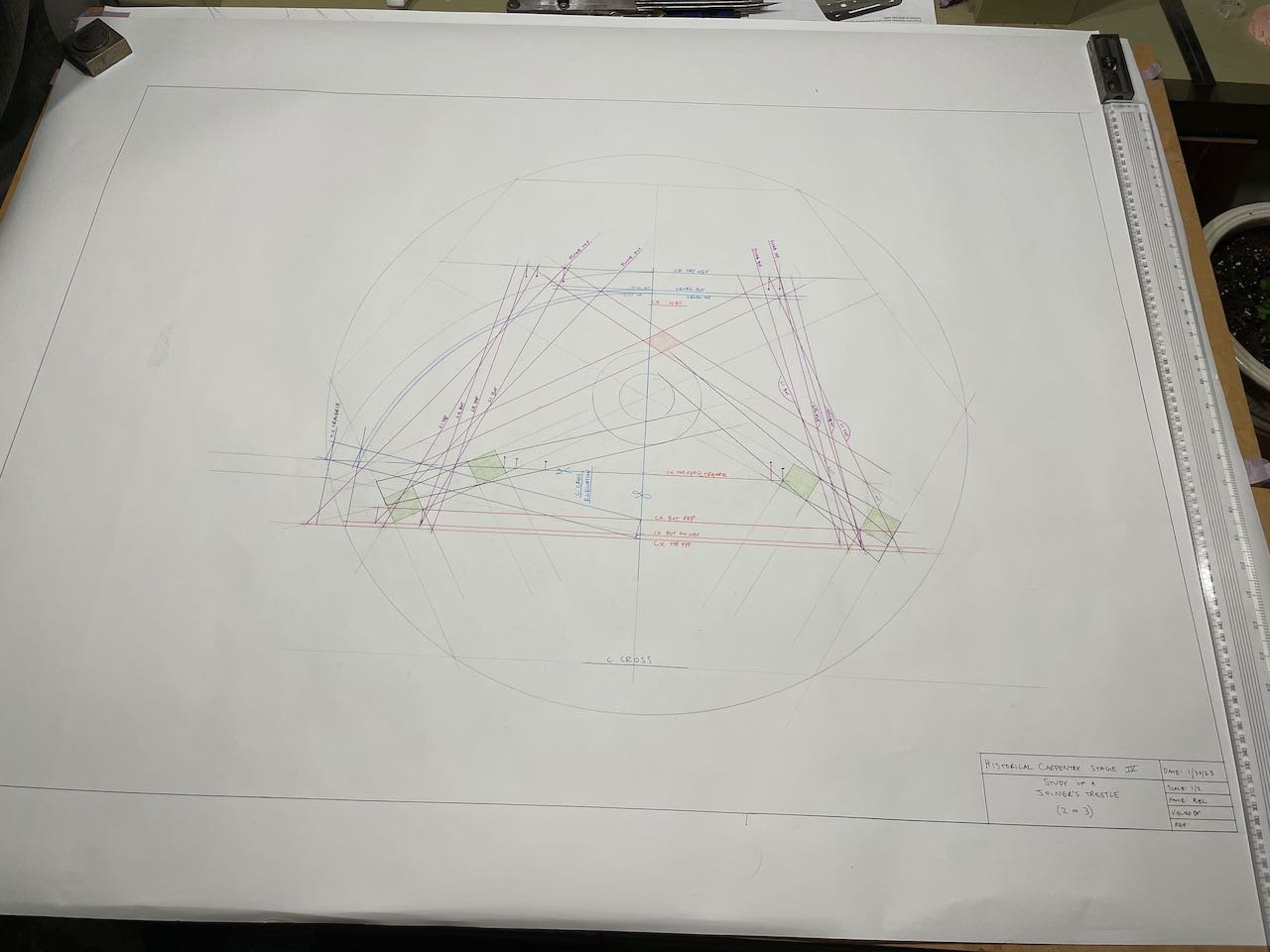
This trestle was a capstone for my studies at the Professional School of Practical Stereotomy. Read more here.
Trestle with Three Internal Planes
A few more (of the many) stepping stones along my journey with stereotomy.
More Study Models
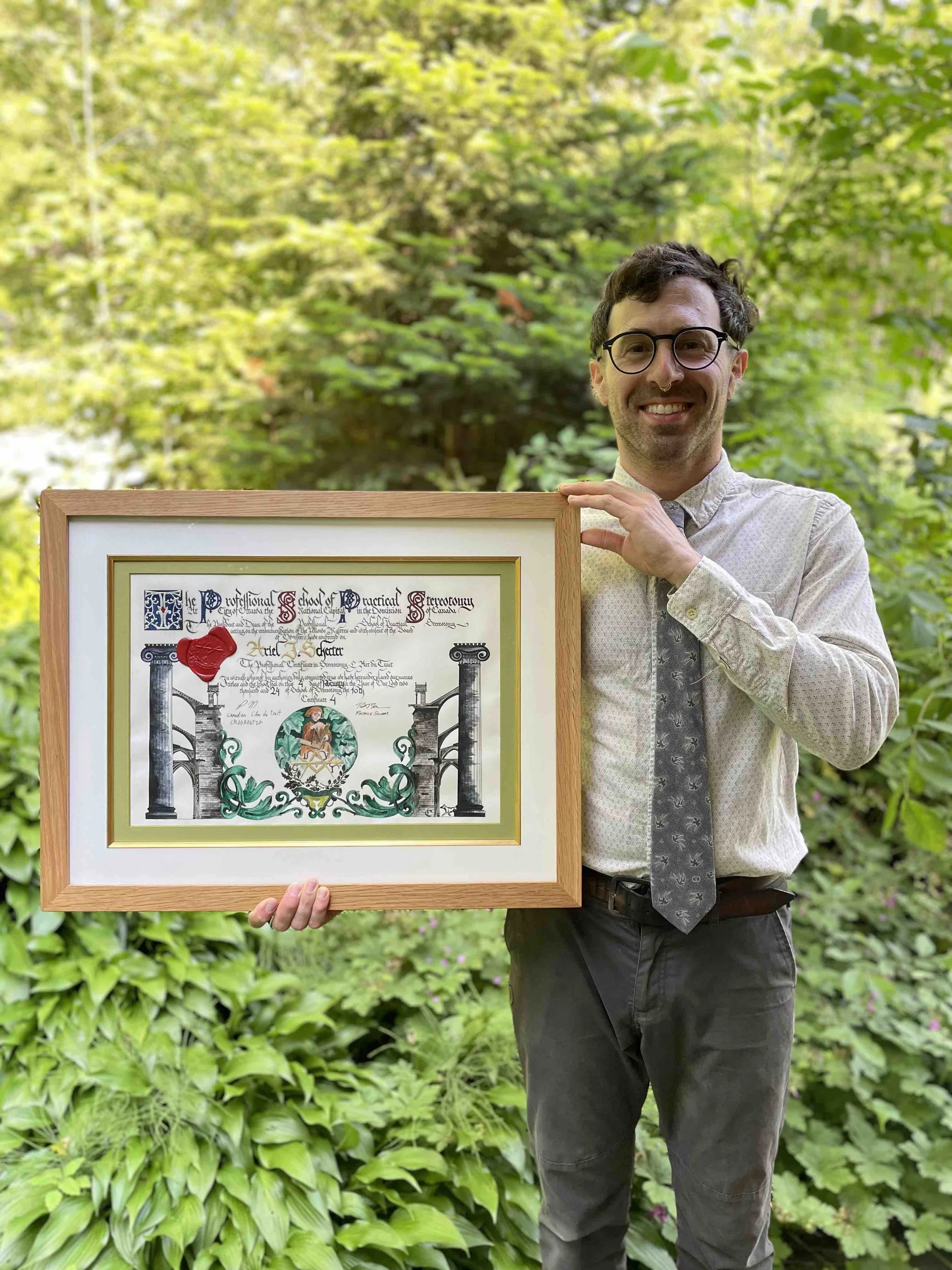
What you see on this page is a body of work completed during my studies of linear stereotomy with Patrick Moore, of the Professional School of Practical Stereotomy. Patrick learned stereotomy in France from a guild known as “Les Compagnons du Devoir,” which has a long and rich history dating back to the middle ages. The name for this particular French lineage of stereotomy is “L’art du Trait.”
This work encompasses 8 years of study, culminating with an elaborate induction piece to become a Fellow and board member of the school.
To learn stereotomy is to learn a new language. Just as some concepts don’t translate easily between languages, stereotomy contains distinctive possibilities that can drastically expand our skill as carpenters.